Keywords
Pre-processing, retinal vessel segmentation, fundus image
This article is included in the Research Synergy Foundation gateway.
Pre-processing, retinal vessel segmentation, fundus image
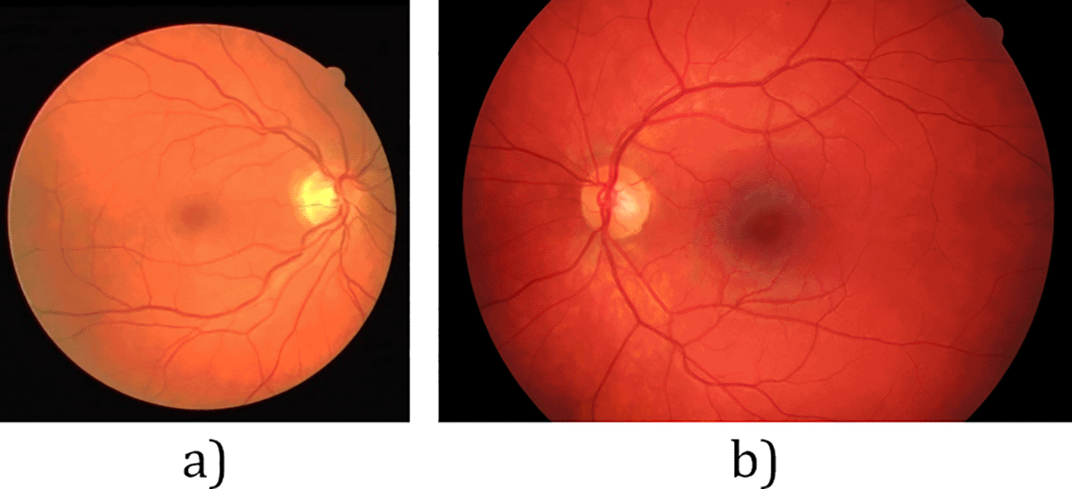
Retinal images play a very important role in ensuring the early detection of symptoms relating to ocular diseases. Early detection will in turn enable timely treatment of eye diseases, which in most cases may significantly decrease the patients’ risk of total vision loss.1 With the global prevalence of eye diseases being gradually on the rise annually, the World Health Organization has encouraged nations to have routine retinal screening in place.2 This is intended to diagnose diseases such as diabetic retinopathy (DR), glaucoma and age-related macular degeneration (AMD) early enough so treatment can be administered before worse disease progression.3 Most hospitals are equipped with fundus cameras that can be used to generate fundus images by imaging a patient’s retina, samples of which are shown in Figure 1.
To assist ophthalmologists in performing efficient and accurate fundus image diagnosis, many studies have been conducted to automatically extract important parameters from a fundus image,4–9 mainly focusing on automatic retinal blood vessel segmentation and then estimating vessel parameters from the segmentation output.10–12 Figure 2 shows a typical flow of blood vessel segmentation procedure.
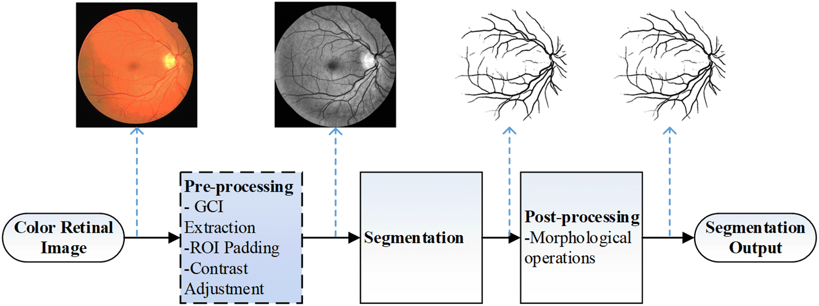
The blue-shaded box indicates the pre-processing steps focused in this study.
For validation of the blood vessel segmentation methods, most researches apply their methods to data from two popular benchmark databases, namely Digital Retinal Images for Vessel Extraction (DRIVE)13 and Structured Analysis of the Retina (STARE).14 However, it should be noted that these databases consist of images which are at a much lower resolution when compared to the fundus images produced by current modern fundus cameras. The images in the DRIVE database have resolution of 565 by 584 pixels while images in STARE have resolution of 700 by 605 pixels. This is because the databases date back to the early 2000s, and the fundus cameras of the time did not have the capability to produce high resolution images.
More recent studies have started to include databases with higher resolution fundus images, such as the High-Resolution Fundus (HRF) database.15 The images in the HRF database have resolution of 3504 by 2336 pixels, markedly higher than images in the DRIVE and STARE databases. Figure 1b shows a sample image from the HRF database.
From Figure 1, it can be seen that the region of interest (ROI) in the DRIVE image is surrounded by dark pixels. However, this is not the case with the image from the HRF database, Figure 1b. The top and bottom edges of the image are not surrounded by the dark area as in Figure 1a. This may result in noisy vessel segmentation output with false positive vessel pixels near the top and bottom images. To the best of our knowledge, this specific problem has not been addressed in the literature.
In this study, we investigated a simple and efficient way to eliminate the noisy pixels in segmentation output for fundus images whose ROIs are not fully surrounded by dark pixels, such as the case with images in HRF database. The proposed method is to be applied in the pre-processing step of retinal blood vessel segmentation workflow, illustrated as the shaded blue box in Figure 2. In order to validate the effectiveness of the proposed pre-processing step, vessel segmentation procedure based on an adapted Bar-Combination Of Shifted FIlter REsponses (B-COSFIRE) filter that we previously published16 is performed on the pre-processed output.
Pre-processing is one of the key steps in retinal blood vessel segmentation techniques, which helps to ensure that the initial fundus image is optimised for the subsequent vessel detection phase. The original red green blue (RGB) format of digital fundus images is not the optimal form for the accurate detection of retinal blood vessels from an image processing point of view due to the natural colours in fundus images that poorly contrast with the retinal background vessels. Issues such as inconsistent illumination across the image, lesser contrast between retinal blood vessels and the retinal background as well as noisy images are other concerns that need to be addressed during the pre-processing step, so that the input image for the vessel segmentation step will be of better clarity in terms of retinal blood vessel structures.
In this study, the pre-processing method employed by Soares17 is used as the basis since it is considered the established method for this purpose.18 Figure 3 illustrates the overview of the pre-processing steps where the first step is to extract the green channel image (GCI) from the color fundus image. The GCI displays a noticeably better vessel appearance, while the red channel image shows low vessel-to-background contrast and the blue channel image displays low dynamic range making the vessels appear almost invisible. This decision to use only GCI is supported by most previously established methods used for segmenting retinal blood vessels from fundus images.18–21 The original code for pre-processing and vessel segmentation using B-COSFIRE can be obtained here.
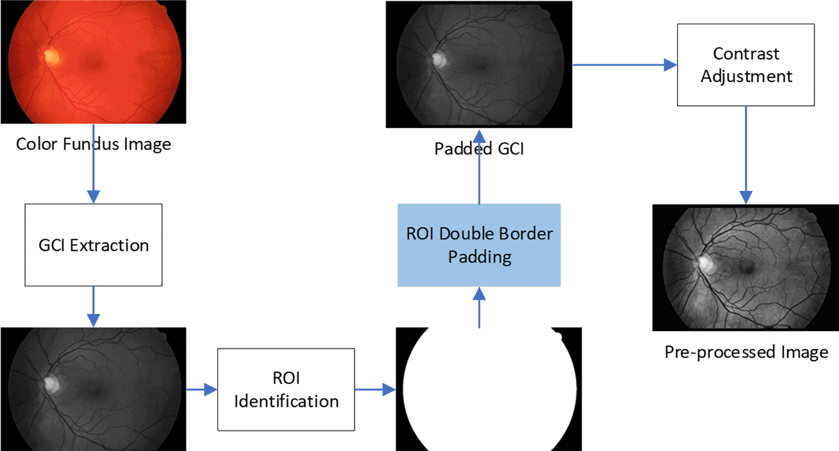
As discussed earlier, the ROI for a fundus image is the colored region inside the circular region on the image. The ROI refers to the non-dark area in the middle of the fundus image, which shows the retina. There is a strong contrast between the ROI and the dark area surrounding the ROI from the extracted GCI. Thus, there is a high probability of detecting false vessel pixels for areas just outside the ROI. To minimise this effect on the segmentation output, Soares suggested that the ROI needs to be identified and expanded by padding it with additional interpolated pixels.17
The procedure starts with converting the fundus image from RGB to the CIELab color scheme. CIELab is a way to represent colours using three numerical values, namely L*, a*, and b*.22 For this ROI identification step, only the L* component or the luminosity component is used as it shows good contrast between the ROI and the black background. An optimum value for a threshold is then estimated using Otsu’s method to transform the L* image into a mask image, as illustrated in Figure 3. The white pixels (pixel value 1) are all the pixels in the ROI, while the black pixels are all the pixels outside the ROI (pixel value 0).
The mask image is then used to locate the pixels that are located at one pixel distance from the outer border of the ROI in GCI using four-neighbourhood connectivity to define the neighbour pixels. After the set of neighbouring pixels is identified, the ROI is eroded by several pixels to minimise the contrast between the ROI and the artificial ROI region (padding) that is added in the next step. Then, the mean value for each of the pixels in the padding obtained earlier is calculated by considering eight-neighbourhood connectivity. Next, each original neighbouring pixel value is then replaced with the mean pixel value calculated in the previous step. This set of altered pixels is then included as part of the ROI, thus effectively enlarging the ROI by one pixel over the original border. These steps are repeated for a few iterations, where each iteration adds a one-pixel border to the ROI. In this study, the erosion size used is 5 pixels while the number of iteration used is 20 iterations, as applied by Azzopardi et al.23 in their B-COSFIRE implementation.
Using this method as proposed by Soares does not add any new pixels to the image, which means the original size is maintained and the top and bottom edges are still not surrounded by the dark pixels. It only converts the grayscale values of pixels surrounding the ROIs with values interpolated from the pixels just inside the ROI border. What we are proposing in this study is the addition of new pixel areas surrounding the original image, thus effectively adding to the resolution of the original image.
In our proposed method, prior to changing the values of the pixels just outside the ROI as in Soares’s method, both the GCI and the mask image are padded with an additional 50 layers of zero-valued (black) pixels on all four borders, referred to as double padding. Using the information from these padded images as the input to the Soares’s padding method, a double-padded image is then produced with the resolution increased by 100 pixels in both height and width. This image is then used to produce a contrast-adjusted image in the next step to highlight the vessel structures. This is the only difference from the original Soares method, which we will refer to as single padding.
After the border of the ROI is padded on the fundus image, the next step is to perform image enhancement on the padded fundus image, so that the vessel structures are enhanced in their appearance. A commonly used pre-processing method for fundus image analysis called contrast limited adaptive histogram equalisation or CLAHE24 is employed in this study. CLAHE is a variation of the histogram equalisation (HE) method, which is a technique used to transform pixels on an image based on its histogram.
This enhanced pre-processing step is performed on all 45 images in the HRF database before they are processed for segmenting the retinal blood vessels. To ensure validity and reliability, the standard performance metrics for vessel segmentation assessment are adopted to quantify the difference in segmentation performance with and without the proposed enhancement method.
As described in the introduction section, the modified B-COSFIRE16 filter is used to extract the vessel features from the pre-processed output images. Sample outputs of the pre-processed images with their corresponding vessel feature images using the single padding and double padding pre-processing methods are displayed in Table 1. By observing the HRF feature image produced using single padding in Table 1, dark lines can be seen on both the top and bottom borders of the vessel feature image. These dark lines will be highly likely to be segmented as false vessel pixels when processed for segmentation. However, the vessel feature image produced using the double padding method does not have these dark lines, thus decreasing the possibility of having a large number of false positive vessel pixels.
 |
Another visible improvement is in terms of the brightness level of vessel pixels in the double-padded vessel feature image as opposed to single-padded. To confirm that double padding is better than single padding for the purpose of vessel segmentation, another comparison is performed on segmentation results using the different padding methods.
Table 2 shows segmentation outputs using the different padding methods, together with their zoomed-in versions. Apart from the apparent improvement in much reduced noisy pixels on top and lower border of the ROI, subtle improvements in vessel appearance are also observed. In general, double padding helps in further enhancing the vessel features, with most vessels appearing brighter compared to single padding outputs, including the smaller vessels. It is found that using double padding in pro-processing results in the successful removal of false positive pixels near the top and bottom image borders of all 45 segmentation output images in the HRF database. In order to quantify the improvement of the segmentation performance when using the proposed method, Table 3 summarises the performance metrics for segmentation using the different padding methods. Following the metric selection in our previous study, four metrics are included, namely Sensitivity (Sn), Specificity (Sp), Balanced Accuracy (B-Acc) and Matthew’s Correlation Coefficient (MCC).
 |
| Padding method | Metric | |||
|---|---|---|---|---|
| Sn | Sp | B-Acc | MCC | |
| Single | 0.6461 | 0.9721 | 0.8091 | 0.6377 |
| Double | 0.7376 | 0.9753 | 0.8564 | 0.7157 |
As expected, the application of double padding results in improved segmentation performance where performance values are increased across all the four considered metrics. This is attributed to the successful removal of the noisy pixels near the top and bottom borders of all images in HRF database, thus decreasing the number of false positive pixels and improving the overall segmentation performance.
In this study, we proposed a simple but effective method to improve blood vessel segmentation performance for images with the ROI reaching the image borders. The simple method of adding additional layer of dark pixels around the image proves to be effective in removing the noisy pixels at the image borders. Quantitatively, the additional padding step also managed to improve all the four considered metrics for vessel segmentation, namely Sensitivity (73.76%), Specificity (97.53%), Balanced-Accuracy (85.64%) and MCC value (71.57%) for the HRF database. This method has only been validated on a single high-resolution fundus image database for now, so in the future more databases should be included for validation to attest the robustness of the proposed methods on multiple databases. The proposed improvement method, while simplistic in nature, could prove to be very effective in increasing overall vessel segmentation performance, particularly for images that are not fully surrounded by dark pixels such as HRF database images.
| Views | Downloads | |
|---|---|---|
| F1000Research | - | - |
|
PubMed Central
Data from PMC are received and updated monthly.
|
- | - |
Provide sufficient details of any financial or non-financial competing interests to enable users to assess whether your comments might lead a reasonable person to question your impartiality. Consider the following examples, but note that this is not an exhaustive list:
Sign up for content alerts and receive a weekly or monthly email with all newly published articles
Already registered? Sign in
The email address should be the one you originally registered with F1000.
You registered with F1000 via Google, so we cannot reset your password.
To sign in, please click here.
If you still need help with your Google account password, please click here.
You registered with F1000 via Facebook, so we cannot reset your password.
To sign in, please click here.
If you still need help with your Facebook account password, please click here.
If your email address is registered with us, we will email you instructions to reset your password.
If you think you should have received this email but it has not arrived, please check your spam filters and/or contact for further assistance.
Comments on this article Comments (0)