Keywords
Microfluidic, electrophoresis, dielectrocphoresis, geometry, microelectrode, protein
Microfluidic, electrophoresis, dielectrocphoresis, geometry, microelectrode, protein
Dielectrophoresis (DEP) has been proven as a versatile manipulation technique commonly used in a microfluidic platform1. DEP technique is commonly used to manipulate dielectric particles in a non-uniform electric field by the induction of DEP force (FDEP)2. Dielectrophoresis is an electrokinetic motion phenomenal occurring when a polarizable particle is put in nonuniform electric fields, and the particle mobility is influenced by the ambient electric field, as well as the characteristics of the dielectric particles or solutions3. Its versatility has provided various benefits for clinical application, laboratory diagnostics and research application4.
In the case of a DEP setting where target bioparticle (particle) such proteins and cells are in the submicro to nano size, the DEP force applied onto the particles will be extreme small. It is because according to the DEP equation (1), the key influence in particle motion by DEP force was determined by the electric field gradient and the particle volume, which was defined by its radius. Therefore, smaller particle will experience smaller DEP force for particle trapping or separation5. In order to compensate for this unchangeable particle radius variable, the microelectrodes geometry design must be optimized to provide an effective and higher performance of DEP response. To achieve of this, according to the equation (1), one of the optimizations of the microelectrodes geometry design that can be done is to design an electrode that can provide a higher electric field gradient to compensate the small particle radius6. Moreover, the optimization may lead to require lower voltage that can circumvent for joule heating effect, while having high throughput performance for higher particle DEP manipulation ability7.
For the case a homogeneous spherical particle in the suspension medium, the general time-averaged DEP force amplitude can be expressed by the classical DEP force as equation (1). εm denoted as the absolute relative permittivity of suspension medium, while ε0= 8.854×10⁻¹² F/mis the permittivity of the vacuum, the spherical particle’s radius is denoted as r or rext,. ERMS is the root-mean-square of the applied electric field in AC, and Re[fCM] is the real part of Clausius-Mossotti (CM) factor2. The equation of the real part of Clausius-Mossotti factor Re[fCM] is given in equation (2).
The subscripts “p” and “m” are referred to particle and medium respectively. inline math and inline math are the complex permittivity with respect to particle and medium which can be defined as in equation (3)8
σp and σm is the electric conductivity of a particle and medium respectively. ω is angular frequency of the applied electric field defined as ω = πƒ, where ƒ is the frequency of the electric field and .
In order to optimizing the electrode geometry and design, there are several geometrical parameters that will be affecting the electric field gradient ∇E2 which are the width of the electrodes and the spacing between the two electrodes9,10.
To further study on this, a rectangular geometry shape electrode has been designed as shown in Figure 1 which is an interdigitated castellated type design which consist of two same-sized electrodes, and these two electrodes are made up of gold material with the thickness of 0.15 µm. The two electrodes were positioned with a spacing gap between them and placed at the bottom of the microfluidic channel, the microelectrode dimension has been shown in Table 1. For 3 main variables with each parameter used to study the optimization of electric field gradient were: 1. the microfluidic channel height (20 µm, 30 µm, 40 µm, 50 µm), 2. the electrode width (20 µm, 40 µm, 60 µm, 80 µm, 100 µm) and 3. the electrode gap spacing (5 µm, 10 µm, 15 µm, 20 µm, 25 µm, 30 µm, 35 µm, 40 µm, 45 µm, 50 µm).
| Features | Value (µm) |
|---|---|
| Channel Width | 130 |
| Channel Length | 370 |
| Electrode Length | 360 |
| Electrode Spacing | 5 |
| Electrode Thickness | 0.15 |
| A | 18 |
| B | 36 |
| C | 36 |
A Finite Element Method (FEM) simulation study was performed by using COMSOL Multiphysics version 5.5 software (RRID: RRID:SCR_014767; URL: https://www.comsol.com/comsol-multiphysics). A 2D space dimension FEM simulation analysis has been carried for this study with only considering the cross-section view of the microfluidic change. Electric currents (ec) physics module was added to defines the electrical potential in the fluid domain and the electric field current was governed by the Ohm’s law continuity equation. The simulation study was carried out in the settings of frequency domain (AC). The governing equations for this frequency domain, electric current, electrical conductivity and relative permittivity are expressed as below:
J denoted as electric current density, σ is electrical conductivity, V electrical voltage, E electrical field, D electric displacement field, ε0 is the relative permittivity of air and εr is the relative permittivity of the fluid respected to the air. By solving these equations, the electric field E in the microfluidic system is calculated and the electric field E is in direct relation to the amount of DEP force according to equation (1).
The cross-section microfluidic and its rectangular geometry electrodes have been created according to the dimension in the Figure 2. Gold material were assigned for both the electrodes with the electrical conductivity, σ = 44.2x10⁶ S/m and relative permittivity, ε = 1, for the medium within the microchannel was a deionized water with its electrical conductivity, σ = 0.0002 S/m and relative permittivity, ε = 78. Under the electric currents (ec) physics module, 10 V peak to peak AC electric potential was set to be applied to the electrodes. The boundaries of one electrode have been input an electric potential V0 = 10V, while the other electrode with its boundaries were input with electric potential V0 = -10 V. The remaining boundaries of the channel were set to be insulated. Extremely fine mesh was generated for this created model. Lastly, a study was generated with electric current model that defines the electrical potential and it is conducted in a frequency domain (AC).
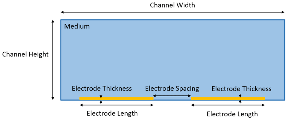
The numerical results such as electrical potential distribution Vpp, electric field distribution V/m and electric field gradient ∇E2 were generated from this model. This numerical study was performed with 5 different channel height (20µm, 30µm, 40µm, 50µm) and with the input of different combination parameters of electrode width and electrode spacing as according to the Table 2.
A parametric study on the geometrical parameters of rectangular shape microelectrode for DEP microfluidic platform has been conducted to identify its optimization microfluidic and electrode design for DEP manipulation of micro to nano particles. In this numerical study, an electric field gradient was generated in the model as shown in Figure 3, by further input of different design variables into the study model such channel height, electrode width and electrode spacing and its parameters to study the optimization of the rectangular microelectrode and identify its optimum design parameters. Electric field gradient is the key identifier for an effective DEP microfluidic platform, therefore in the generation of the electric field gradient result in this cross-section microfluidic model, only the horizontal component of the electric field gradient is considered.
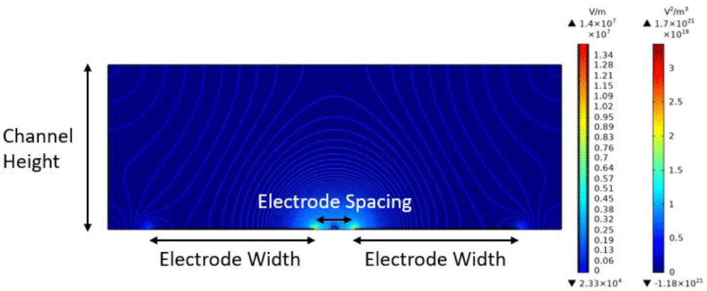
The result shows the electric field gradient distribution and the electric field contour.
According to the 3D plot result from Figure 4 has shown that the electric field gradient is exponentially increased when the applied peak-to-peak voltage is increased. However, the electric field gradient remained unchanged to the increase of applied frequency. Although the frequency has not contributed to the electric field gradient but note that it is still an important factor that influence the particle, as the particle DEP response is highly dependent on applied frequency and which is governed by the equation (2) and equation (3)11. This result has shown that the applied voltage has a substantial influence on the electric field gradient, however the applied frequency will have no effect on the electric field gradient. From the generated 3D plot of all the 4 different channel heights as shown in Figure 5, it has been shown in all the graph that the electric field gradient is gradually decreasing when the electrode spacing is increased and the electric field gradient had a drop at certain point when the electrode width increased beyond 40µm and 80µm.
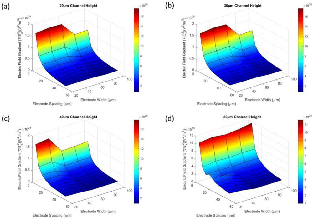
The 3D plots generated with MATLAB R2019b.
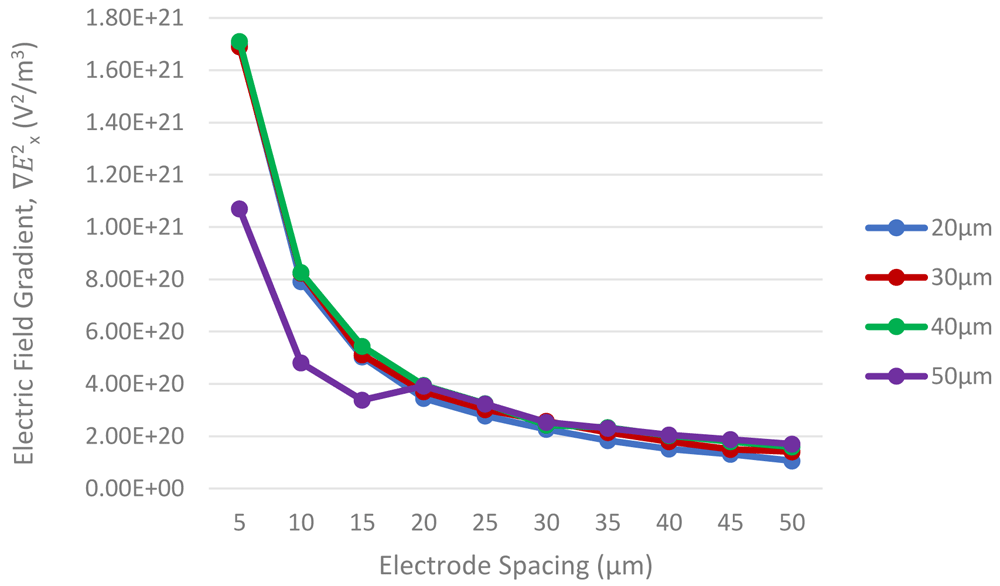
Firstly, for channel height influencing on ∇E2x values are as shown in Figure 6. As observed from the graph, the difference in channel heights (20 µm, 30 µm, 40 µm) have similar pattern and have very little difference on the electrode’s ∇E2x values. The ∇E2x values gradually increased when the electrode spacing increased. Only the channel height of 50µm showed lowest ∇E2x values at the beginning range of electrode spacing from 5 µm to 15 µm. Further to investigate, extend on channel height from 5 µm to 100 µm, with width of electrode 20 µm and electrode spacing 5 µm kept constant as shown in Figure 8. The ∇E2x values have observed a fall between 40 µm to 70 µm channel height. Therefore, the optimum channel height design should be 40 µm.
For the electrode widths results as shown in Figure 7, when the channel height is 20µm and 30µm, the ∇E2x values for different range of electrode widths are in the same pattern. It has been shown that when the electrode width exceeded 60µm, the ∇E2x values have dwindled about 64% drop in ∇E2x value. For channel height 40µm the drop in ∇E2x values have started early at 40µm electrode width. However, the electrode widths were not much influence on the ∇E2x values when the channel height reached 50µm, but it has been the least amount of ∇E2x values, it has about 63% less ∇E2x values compared to other channel, since then the ∇E2x values were not much fluctuated and constantly stayed within its ∇E2x range. The optimum design for the electrode width is within 60µm and channel height within 30µm.
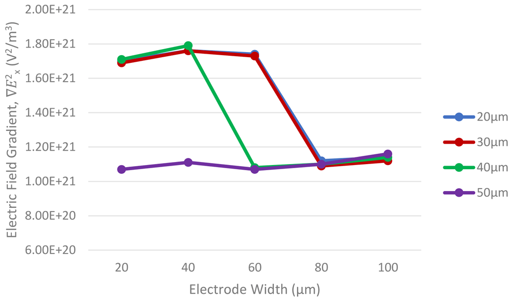
Based on the simulation results, the optimum geometrical parameters for rectangular shape electrode design for the strongest DEP force was identified. In this simulation and parametric studies were only focused on the DEP force and did not include other factors such as hydrodynamic forces, joule heating effects, particles Brownian motion in the microfluidic device. As according to this study, 1. The applied voltage has significant influence on electric field gradient, ∇E2x, however the frequency will not have effect on electric field gradient, nonetheless it is strongly responsible to the DEP response of the particle based on the polarizability between the medium and particle, 2. For the optimum design considerations for rectangular shape microelectrode, the electrode width is advised to fall below 60µm and 3. the channel height should below 30µm to obtain the strongest DEP force for particle manipulation in this microfluidic design.
| Views | Downloads | |
|---|---|---|
| F1000Research | - | - |
|
PubMed Central
Data from PMC are received and updated monthly.
|
- | - |
Is the work clearly and accurately presented and does it cite the current literature?
No
Is the study design appropriate and is the work technically sound?
Partly
Are sufficient details of methods and analysis provided to allow replication by others?
Partly
If applicable, is the statistical analysis and its interpretation appropriate?
Not applicable
Are all the source data underlying the results available to ensure full reproducibility?
Partly
Are the conclusions drawn adequately supported by the results?
Partly
References
1. Torres-Castro K, Honrado C, Varhue WB, Farmehini V, et al.: High-throughput dynamical analysis of dielectrophoretic frequency dispersion of single cells based on deflected flow streamlines.Anal Bioanal Chem. 2020; 412 (16): 3847-3857 PubMed Abstract | Publisher Full TextCompeting Interests: No competing interests were disclosed.
Reviewer Expertise: Microfluidic systems coupled with electrokinetics (DEP), mechanical separations, impedance cytometry and acoustofluidics for LOC and OoC applications.
Is the work clearly and accurately presented and does it cite the current literature?
Partly
Is the study design appropriate and is the work technically sound?
Yes
Are sufficient details of methods and analysis provided to allow replication by others?
Partly
If applicable, is the statistical analysis and its interpretation appropriate?
Yes
Are all the source data underlying the results available to ensure full reproducibility?
Partly
Are the conclusions drawn adequately supported by the results?
Partly
References
1. Ur Rehman A, Zabibah RS, Kharratian S, Mustafa A: Microfluidic device for the Separation of non-metastatic (MCF-7) and non-tumor (MCF-10A) breast cancer cells using AC Dielectrophoresis.J Vis Exp. 2022. PubMed Abstract | Publisher Full TextCompeting Interests: No competing interests were disclosed.
Reviewer Expertise: Microfluidics, Dielectrophoresis and COMSOL simulation
Is the work clearly and accurately presented and does it cite the current literature?
Yes
Is the study design appropriate and is the work technically sound?
Yes
Are sufficient details of methods and analysis provided to allow replication by others?
Partly
If applicable, is the statistical analysis and its interpretation appropriate?
Yes
Are all the source data underlying the results available to ensure full reproducibility?
Yes
Are the conclusions drawn adequately supported by the results?
Yes
Competing Interests: No competing interests were disclosed.
Reviewer Expertise: Microfluidics, Dielectrophoresis, Cell manipulation
Is the work clearly and accurately presented and does it cite the current literature?
Yes
Is the study design appropriate and is the work technically sound?
No
Are sufficient details of methods and analysis provided to allow replication by others?
Partly
If applicable, is the statistical analysis and its interpretation appropriate?
Partly
Are all the source data underlying the results available to ensure full reproducibility?
No source data required
Are the conclusions drawn adequately supported by the results?
Partly
Competing Interests: No competing interests were disclosed.
Reviewer Expertise: I have 8 years of experience in a lab on a chip applications special in Dielectropgoresis
Alongside their report, reviewers assign a status to the article:
| Invited Reviewers | ||||
|---|---|---|---|---|
| 1 | 2 | 3 | 4 | |
|
Version 1 11 Feb 22 |
read | read | read | read |
Provide sufficient details of any financial or non-financial competing interests to enable users to assess whether your comments might lead a reasonable person to question your impartiality. Consider the following examples, but note that this is not an exhaustive list:
Sign up for content alerts and receive a weekly or monthly email with all newly published articles
Already registered? Sign in
The email address should be the one you originally registered with F1000.
You registered with F1000 via Google, so we cannot reset your password.
To sign in, please click here.
If you still need help with your Google account password, please click here.
You registered with F1000 via Facebook, so we cannot reset your password.
To sign in, please click here.
If you still need help with your Facebook account password, please click here.
If your email address is registered with us, we will email you instructions to reset your password.
If you think you should have received this email but it has not arrived, please check your spam filters and/or contact for further assistance.
Comments on this article Comments (0)