Keywords
Tissue cellular quantification, spatial cellular profiling, cell-cell interactions, scatterplot, histo-cytometry, image cytometry
This article is included in the NEUBIAS - the Bioimage Analysts Network gateway.
This article is included in the Bioinformatics gateway.
Tissue cellular quantification, spatial cellular profiling, cell-cell interactions, scatterplot, histo-cytometry, image cytometry
The identification, localization and quantification of cell subsets in tissue is a difficult but essential task for biologists to understand spatial cellular organization in different settings (e.g. homeostasis vs inflammatory diseases or cancer). Advances in optical microscopy allow image acquisitions with more than 10 channel measurements using spectral fluorescence imaging or multiplex imaging combined with z-axis optical slices of tissue sections ranging from 10 µm to more than 200 µm when clearing methods are used1–4. Analysis of such complex images is very challenging due to the size and complexity of data. It requires image segmentation in 3D that can be further improved using deep learning-based segmentation5–7. Then, like flow cytometry, complex image analysis can benefit from scatterplot representations that allow to gate cells of interest2,8. Surprisingly, in existing software, this scatterplot representation is rarely interactive with the image itself, although this would allow to locate selection results back into the image but also to filter or correct results and fine-tune the gates defining cell populations to obtain in return a better visualization of them into the image.
To this end, we developed the Shiny Analytical Plot of Histological Image Results (SAPHIR), an R/Shiny application for the quantitative analysis of tissue section images. Since image segmentation is a complex task in continuous development and highly dependent on image quality and information, the integration of a single type of segmentation method in an image analysis application is not necessarily recommended. Therefore, we decided to separate segmentation from SAPHIR, but we provided two Fiji macro examples with associated images, which can be used to perform this task before running SAPHIR. SAPHIR offers many features such as interactive scatterplots with the image and data filtering and correction as described below.
The segmentation required to use the application SAPHIR has been carried out under Fiji9, with custom-made macros, which are available on GitHub in the Demonstration Files. Cell nucleus detection was used for segmentation and fluorescence intensity signal of each channel within a circular ring around nuclei was determined to define cell of interest (COI) phenotype. In addition, regions of interest were defined using DBSCAN (optional)10. The segmentation process of the image to be analyzed should create a csv result file containing the channel intensity values (ranging from 0 to 255) and, if required, the positioning (x, y, z) linked to each COI. Another file, termed ROI.zip, should contain the image contour of each COI. Importantly, many other morphological measurements like area, roundness, or solidity as well as other information (COI belonging to a region of interest, COI interaction with other cells, COI centroid position) can be added to the segmentation result file. Finally, the minimal requirements to run the application are the image in TIFF with multiple channels and optionally slices, the segmentation result file with COI identity in csv and the roi.zip file containing contours of each COI. A legend file with all channel information can also be provided (optional).
SAPHIR is built in the R programming language, version 4.0.2, and uses many packages available on CRAN (e.g. shinydashboard, ijtiff, magick, ggplot2, plotly) and one package (EBImage) available on Bioconductor. It has been tested on macOS and Windows 10. A user flowchart from image acquisition to obtention of quantitative data of COI with SAPHIR is shown in Figure 1.
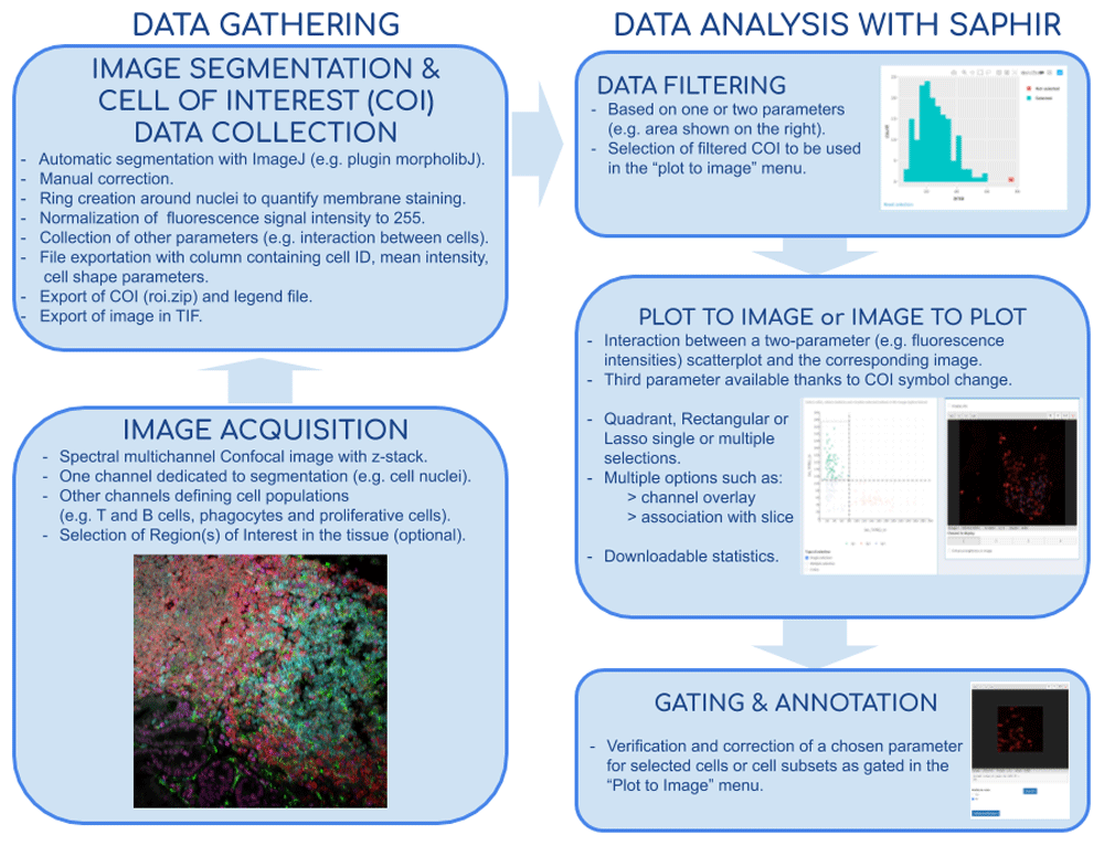
The first step of SAPHIR is either to run a segmentation program to obtain appropriate files or to load the three required files (image.tif, roi.zip, results.csv) and if needed the legend (csv file) in the “select your results” menu of the application. Here, result, region of interest (ROI) and legend files were obtained with an in house-made segmentation macro developed under Fiji.
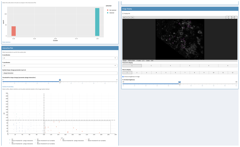
The first tab of the “Plot to Image” menu is shown in Figure 2 and allows the users to filter their data depending on one or two parameters displayed on histogram or scatterplot, respectively. This can be used to remove cells that have been badly segmented. Indeed, such cells display an aberrant area or volume (doublets or aggregates in red in Figure 2). Here, only cells within the Gaussian curve were retained (in blue in Figure 2). This can also be used to work only on given subpopulations filtered based on their location, interaction with other cells or other criteria (see use case section below). Then, filtered cells can be separated into subsets thanks to a two-parameter (most often channel intensities) scatterplot (Figure 3A). In addition, users can add a third parameter that is displayed on the scatterplot through a change of symbol shape for each COI beyond a threshold defined by the users for a given parameter value (Figure 3A).
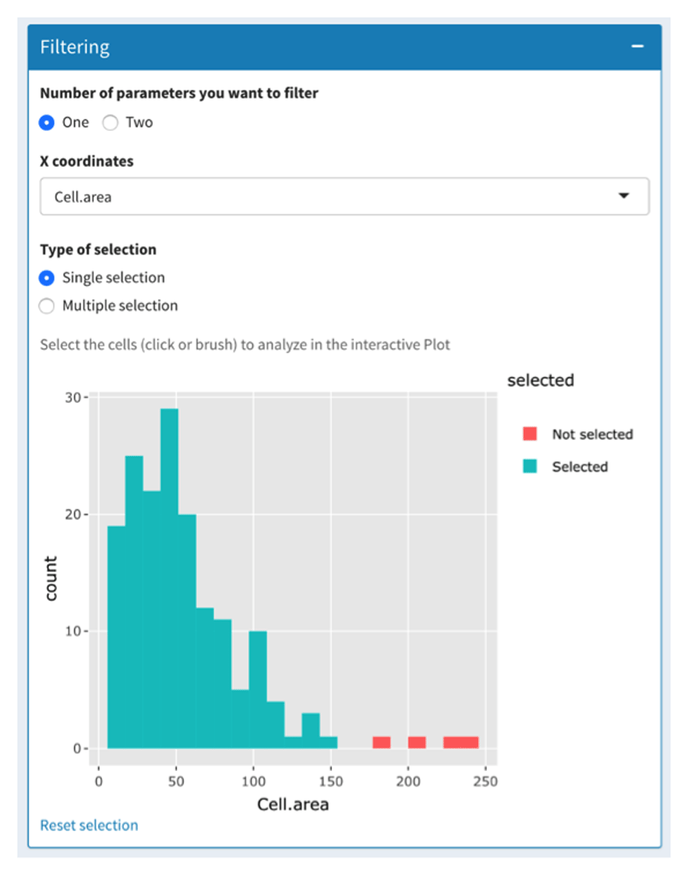
The data-filtering tab allows the selection of cells to be analyzed based on one or two parameters. Based on the cell area parameter, only cells that displayed a conventional cell area (in blue) were selected. Badly segmented cells (large area in red) were discarded.
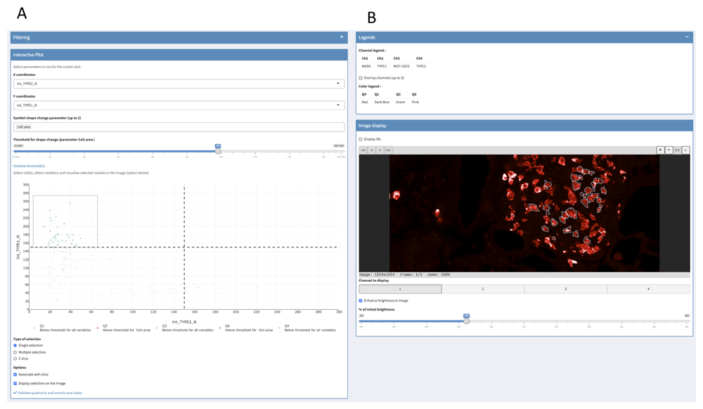
(A) Scatterplot of two channel intensity parameters used to gate COI. User can add a third parameter that is displayed on the scatterplot through a change of symbol shape for COI beyond a threshold defined by the user. (B) Visualization of selected cells in the image. Some of the available options are shown (displayed channel(s), channel overlay, cell identity number, brightness).
Gating can be made easily with quadrants, rectangles and lassos in single or multiple selection mode. Interactivity between scatterplot and image is optional to avoid slow interaction when high-resolution images are used. In the latter case, we recommend users to perform their gating before allowing their selection to be shown in the image by ticking the appropriate box. Users can easily change the slice and the displayed channels with buttons to monitor selected COI spatial distribution and fluorescence intensity in the image (Figure 3B). Moreover, several options are available such as cell identity display or channel overlay (Figure 3B). Finally, statistics of the gated COI are downloadable, and gates are saveable for further analyses.
The SAPHIR menu “image to plot” allows to select a region in the image and to display cells of this region on a two-parameter scatterplot (Figure 4).
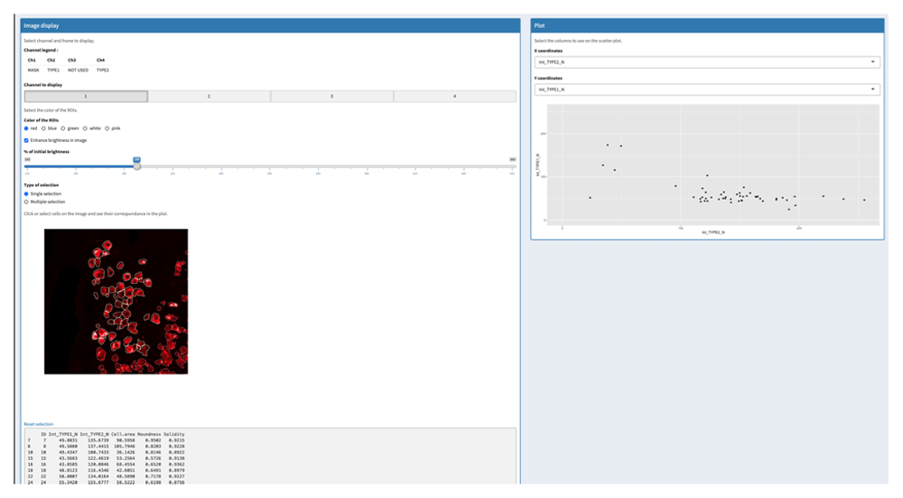
Selection of one region in the image (left) and visualization of COI of this region in a corresponding scatterplot where two parameters are displayed (right).
Finally, the menu “Annotation” allows, based on the previous analyses, correction of the data from the result csv file but also from the scatterplot-gated cells when saved in the “plot to image” menu. For each selected cell, a cropped image of this cell is displayed, and users can change its parameters if necessary (Figure 5).
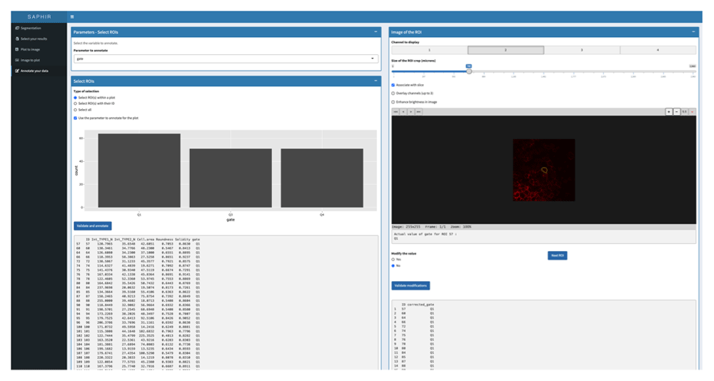
The results to annotate can be selected based on the Plot to Image scatterplot gated cells that have been previously saved (left panel). Each cell of the selection can be visualized in the image (right panel) with the possibility to change image size (magnification), the displayed channel(s), the slice (z optical section) and the brightness. Based on the different analysis, results for the selected COI can be modified and final results saved and exported.
To show the usefulness of our application, we used it on a project that aimed to characterize the interaction between phagocytes and proliferative immune effector cells in murine Peyer’s patches (PP), i.e. B and T cells. PP are immune inductive sites distributed along the small intestine in charge of sampling noxious antigens and mounting an immune response against them. In PP, antigens are taken up by phagocytes that, upon stimulation, migrate in the T cell zone and its periphery to interact with and prime naïve T cells. The periphery of the PP T cell zone is indeed an area of intense proliferation of immune effector cells after stimulation, suggesting that this region is a privileged site for their activation11. We therefore decided to examine the evolution of proliferative cell number, to determine their identity (B or T cells) and to analyze their interaction with migratory phagocytes during the course of the stimulation.
We used SAPHIR application and two ImageJ macros, which are available on GitHub in the Demonstration Files. The first macro allows the counting of proliferative cells through segmentation of Ki-67+ nuclei, provides their identity through analysis of T and B cell staining of Ki-67+ cell membrane, and analyses their interaction with phagocytes. The second macro identify the area of high density in proliferative cells as ROI, thanks to the DBSCAN algorithm and determine whether previously analysed cells belong to this ROI.
Then, SAPHIR application allowed us to integrate these data and provided scatter plots and statistical analyses. Thus, the filtering tab was used to select only proliferative cells belonging to the ROI (Figure 6, upper left). Then, ROI-proliferative cells were split into B and T cells using the scatter plot (Figure 6, lower left). Finally, we used the “symbol shape change parameter” option to highlight ROI-proliferative cells that interacted with phagocytes. This clearly showed that in the ROI, there were more proliferative T cells than B cells that interacted with phagocytes. Exportable statistical tables confirmed this observation. Selecting these T cells, we could localize these cells interacting with phagocytes directly into the image (Figure 6, right).
Upper left: Cells belonging to the proliferative area of the PP T cell zone were selected using the filtering tab. Lower left: ROI proliferative cells were split into T and B cells on the scatterplot and phagocyte-interacting cells highlighted thanks to the symbol shape change parameter (circle). Right: T cells selected in the scatter plot in the lower left (orange) are visualized in the image (magenta contour).
The SAPHIR application provides a simple and user-friendly interface to obtain quantitative data from tissue images as well as COI positioning in the tissue. It is based on the interactivity between quantitative data and image to simplify the analysis and limit bias. Further developments of SAPHIR will include use of pyramidal images to minimize loading and analysis time and unsupervised clustering methods for scatterplot generation12.
SAPHIR is provided with segmentation data from two demo pictures (https://github.com/elodiegermani/SAPHIR/tree/master/Demonstration%20files): one with only two intensity channels to test the application in a very easy and quickly way, and a more complex one with 6 intensity channels, 12 slices and two additional parameters (belonging to a ROI and cell-cell interaction) for advanced testing of the application.
These data are parts of several projects conducted in the Center of Immunology of Marseille-Luminy (France). Acquisition of the images was made with spectral confocal microscopy and analyzed with Fiji with the provided macro.
Source code available from: www.github.com/elodiegermani/SAPHIR
Archived source code as at time of publication: http://doi.org/10.5281/zenodo.408889913
License: GNU General Public License v3.0
| Views | Downloads | |
|---|---|---|
| F1000Research | - | - |
|
PubMed Central
Data from PMC are received and updated monthly.
|
- | - |
Provide sufficient details of any financial or non-financial competing interests to enable users to assess whether your comments might lead a reasonable person to question your impartiality. Consider the following examples, but note that this is not an exhaustive list:
Sign up for content alerts and receive a weekly or monthly email with all newly published articles
Already registered? Sign in
The email address should be the one you originally registered with F1000.
You registered with F1000 via Google, so we cannot reset your password.
To sign in, please click here.
If you still need help with your Google account password, please click here.
You registered with F1000 via Facebook, so we cannot reset your password.
To sign in, please click here.
If you still need help with your Facebook account password, please click here.
If your email address is registered with us, we will email you instructions to reset your password.
If you think you should have received this email but it has not arrived, please check your spam filters and/or contact for further assistance.
Comments on this article Comments (0)